Vehicle: 2003.5 BMW M3 Coupe
Install Date: Tuesday, August 15, 2006
|
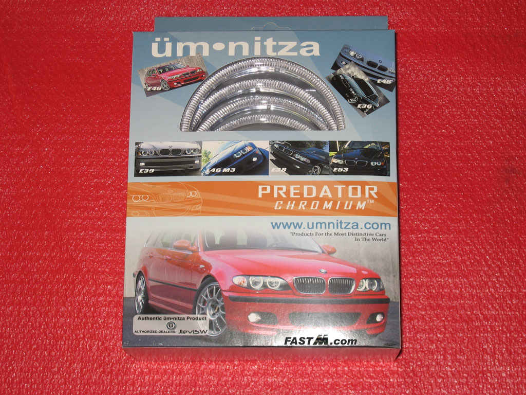
Related Link: umnitza Predator Orion V2 Angel Eyes üm•nitza Predator™ Chromium™ Angel Eyes NOTE: This DIY guide was created using the umnitza Predator Chromium Angel Eyes only. Not for any other
kit. Tools Required
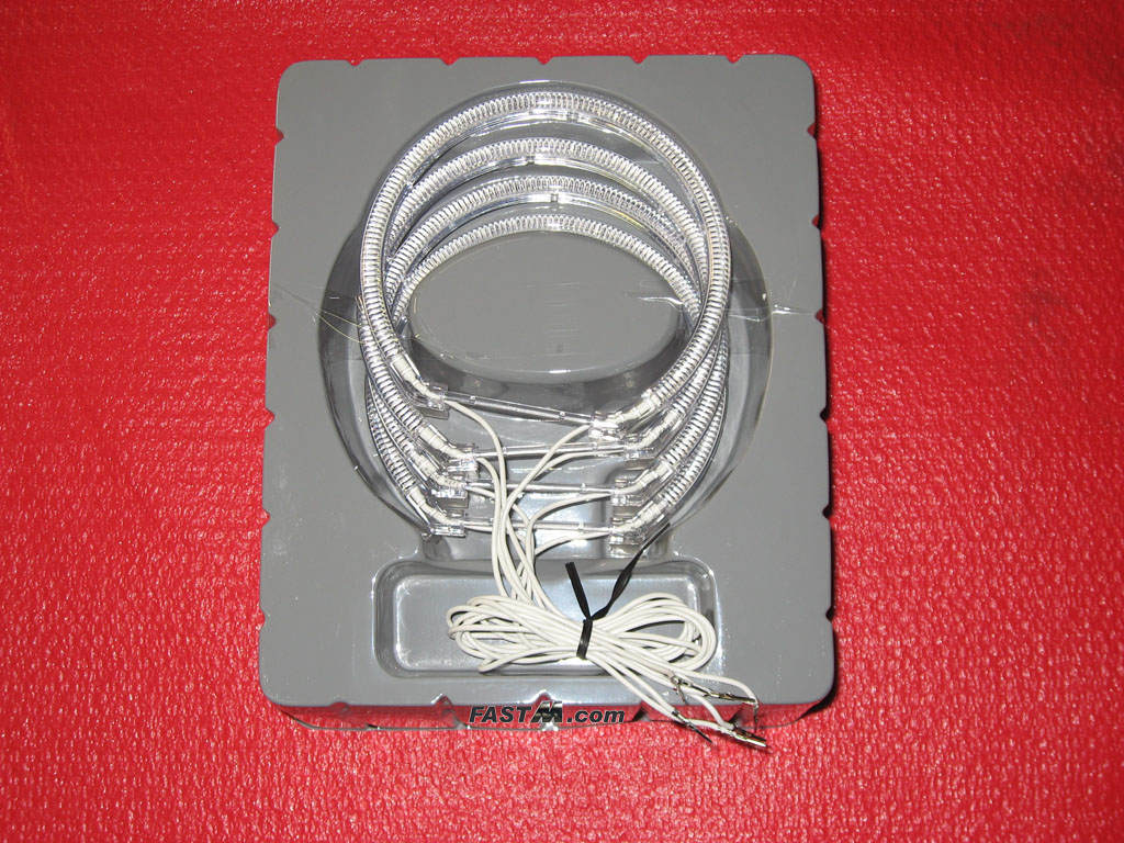
Parts
Click On An Image To See It In Full Size
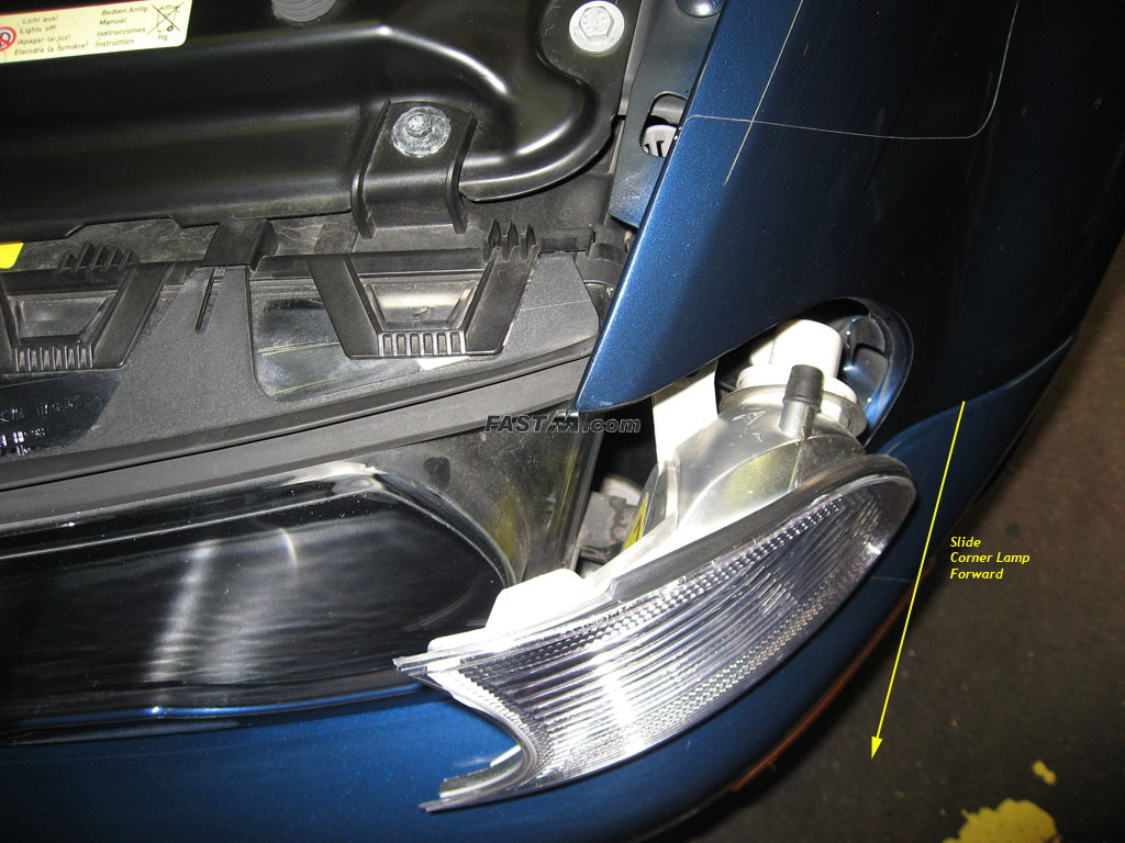
Installation Install Time: (anywhere from 30-90min., if you had to do it a second time it will be much quicker)Before you begin: Step 1. Headlight lense removal 1a) Remove the turn signal corner lamp. Use a Philips Screw Driver to loosen the retaining screw as pictured below. The screw does not come out so
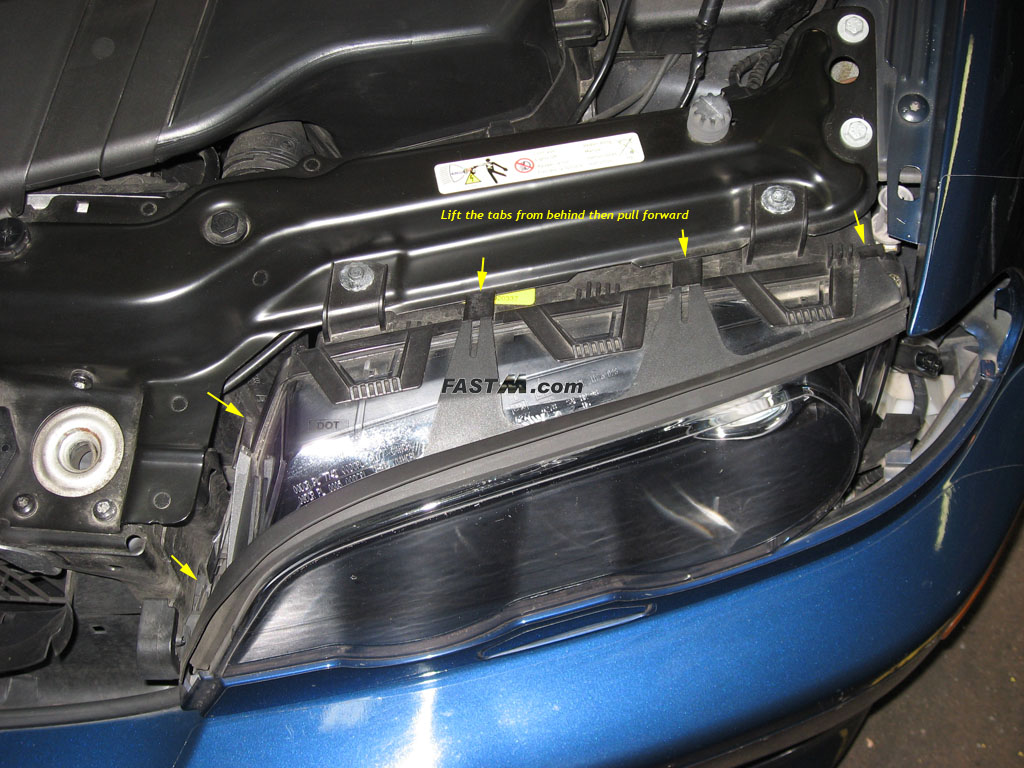
don't keep turning or you'll be turning forever. Once loosen, slide the corner lamp forward and undo the bulb connector. Set the lamp aside. 1b) Remove the rubber trim surrounding the top/side of your headlight. You can easily undo the top 3 tabs with your fingers by lifting the tabs from behind.
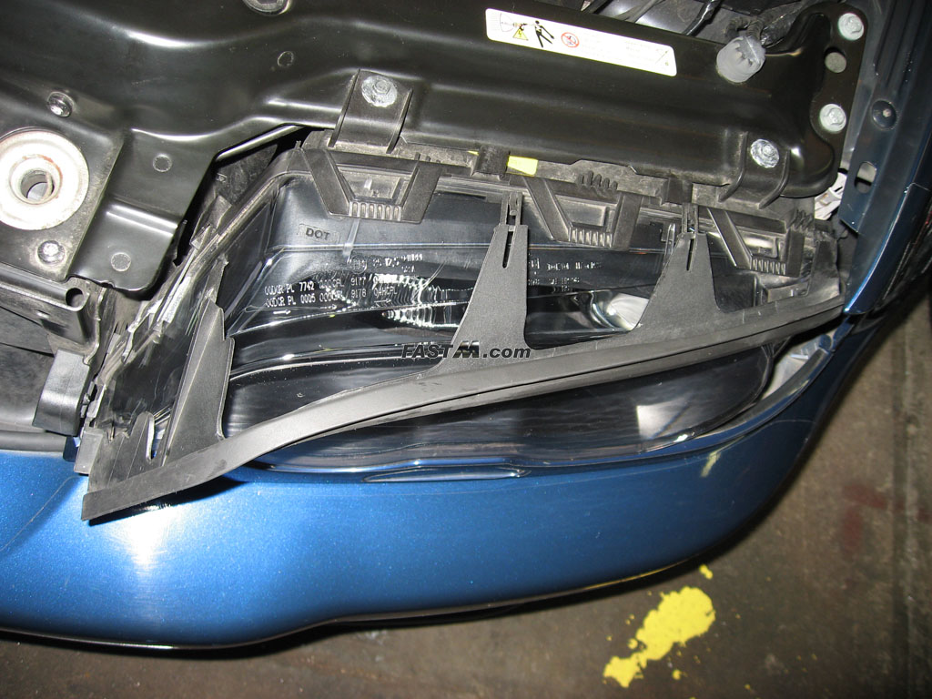
The two tabs on side might be easier with a flat head screw driver. 1c) Remove the lower painted headlight trim. If you have the cold weather package with the headlight washer like I do, it will be easier if you did not remove
the entire trim. Start by unlatching the trim from the end closest to the grill then the latch that is visible from where the corner lamp was removed. To unlatch you
simply reach from behind and unhook it similar to how your removed the rubber trim. If you have the headlight washer, you do not need to disconnect it, just tilt the
trim piece out as far as you can. That should give you enough clearance. If you do not have the headlight washer it's up to you if you want to remove it entirely or
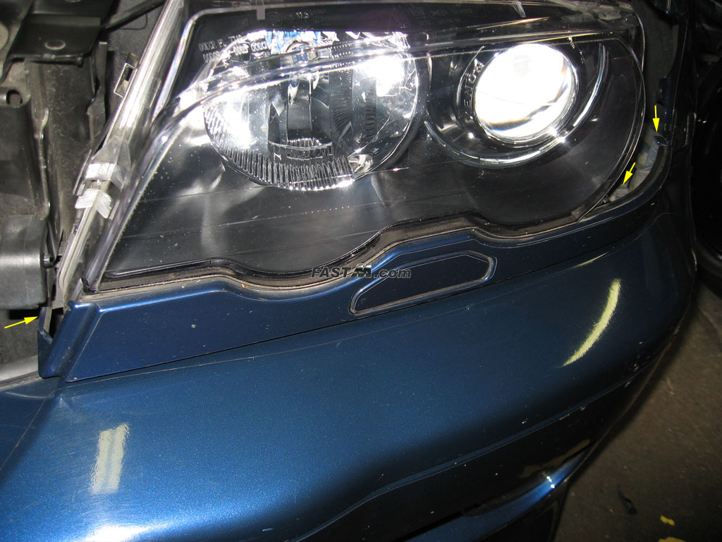
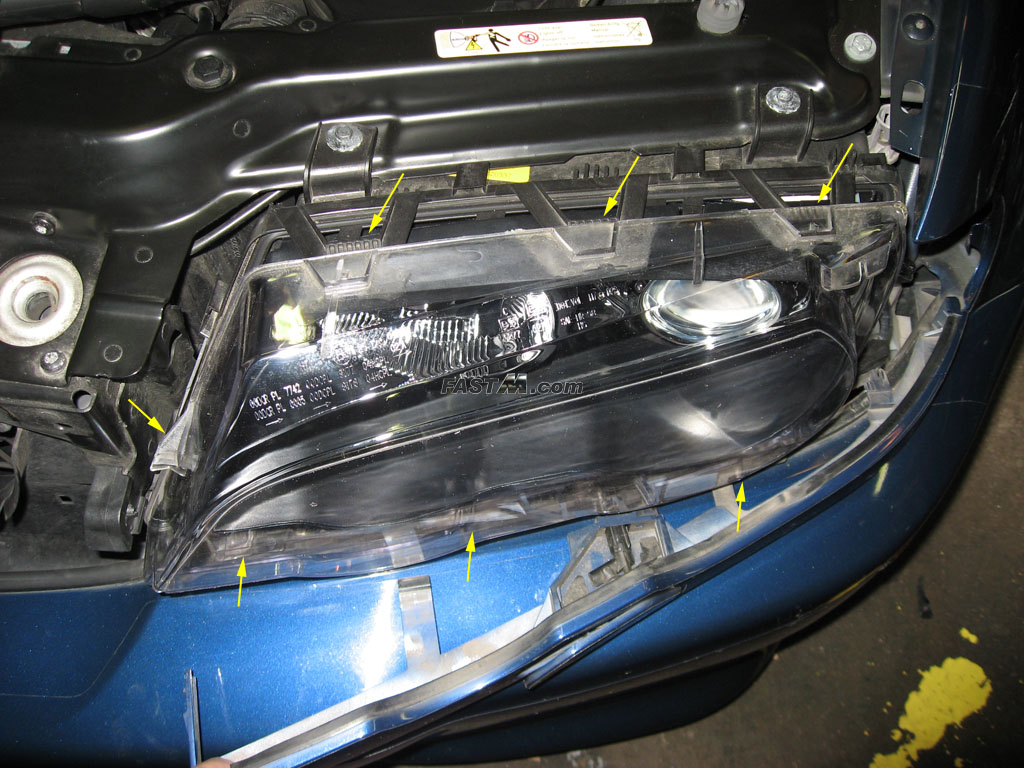
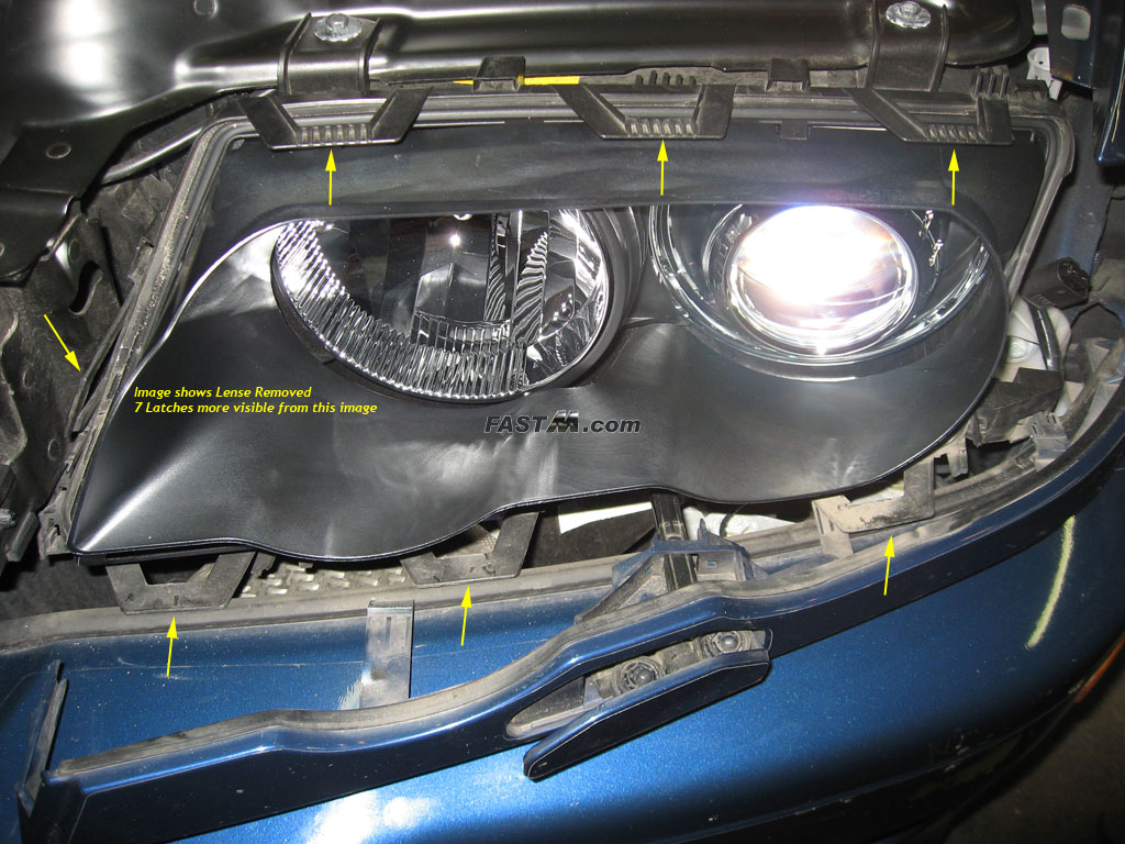
just tilt it out. 1d) Remove the clear headlight cover lense. Tools aren't really necessary here. There are three plastic tabs on top, one on the side, and three on the bottom
that must be unlatched. Carefully pull up on each tab till it releases from lense. As you work your way around each tab you should be able to remove the lense by sliding
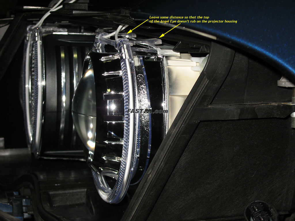
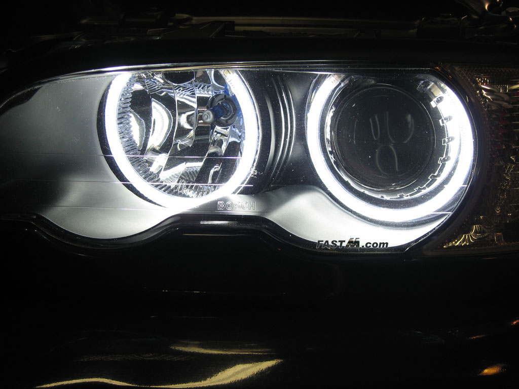
it out. 1e) Remove the OEM inner trim bezel. The bezel simply pulls straight out. No tools needed. Step 2) Mounting üm•nitza Predator™ Chromium™ Angel Eyes Rings 2a) Mount the Angel Eye Ring to the DRL (Day Time Running Lights, also called High Beam Flasher). At the top of the reflector is a lip. Simply slide the alligator
clip at the top of the Angel Eyes onto the top of the reflector lip. See image below for proper spacing of the clips. You do not push both clips all the way in, only
the inner clip (closest to grill) is pushed all the way while the other clip (closest to the Bi-Xenon projector) has some spacing. The easiest way to do this is to
slide both clips in all the way then pull the clip closest to the projector out till the inner lip of the clip stops it from coming out any further. Now look over the
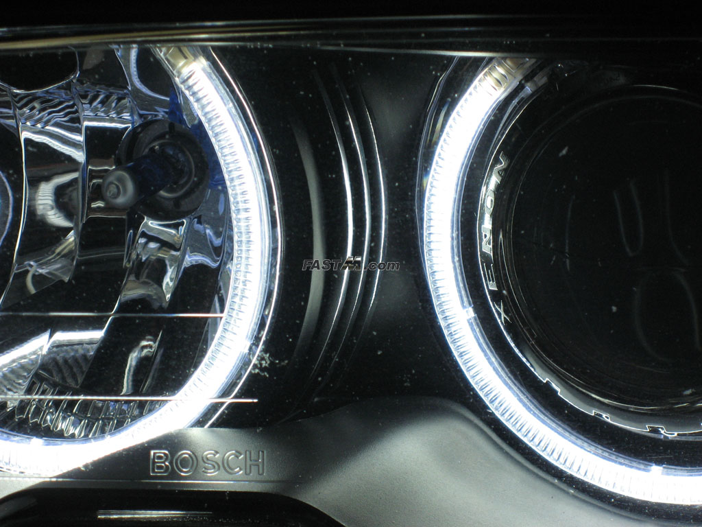
Angel Eye ring to make sure it's even all the way around and lined up. 2b) Mount the Angel Eye Ring to the Bi-Xenon projector. This one can be tricky. You have to make sure you do not push the clip all the way in otherwise it
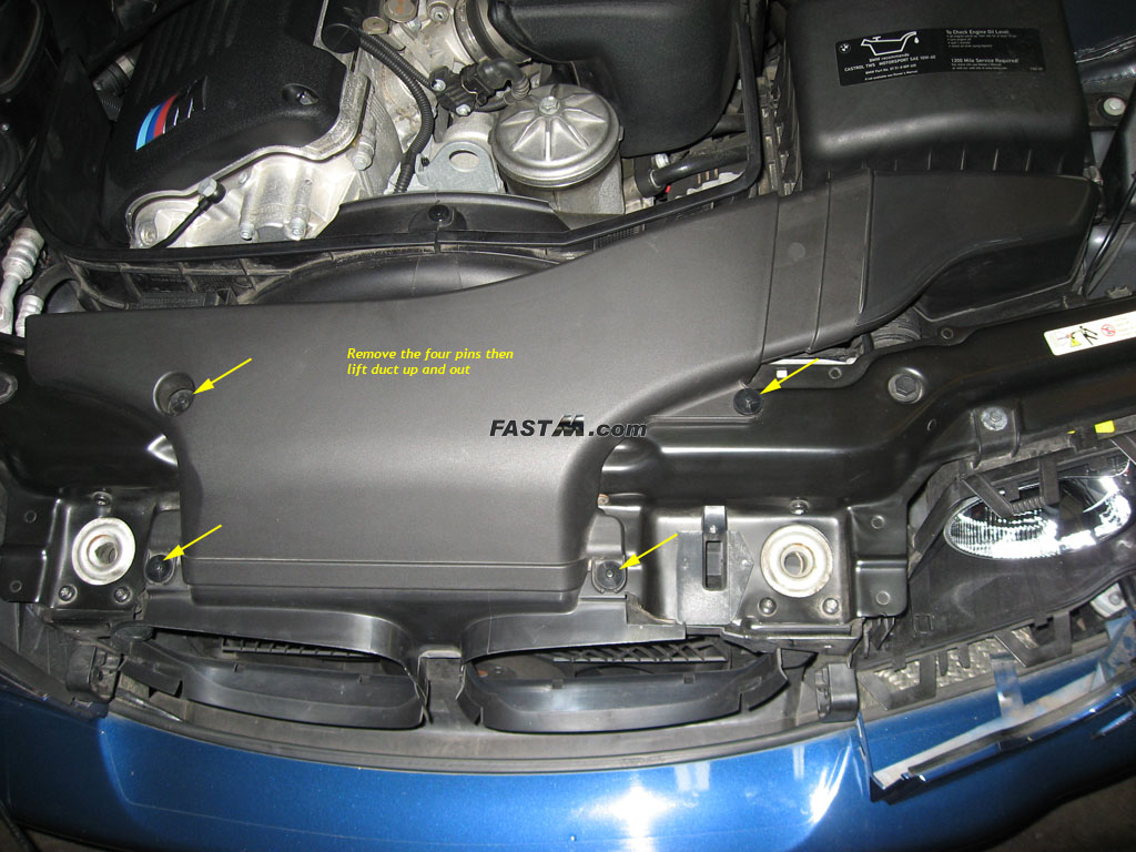
will touch the top of your projector housing. Simply push it till it gets within 1-2mm from the top of the projector housing. Don't worry as it will not fall off. 2c) (Optional) Remove the intake duct from the air box. This will provide additional room to work behind the driver's
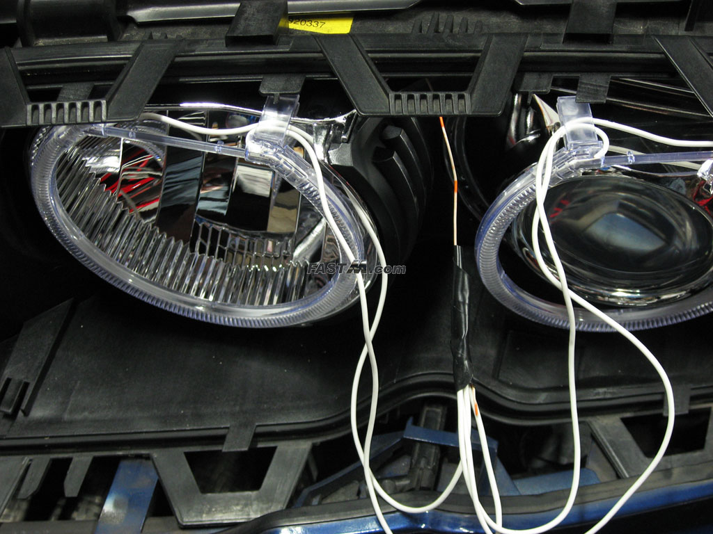
headlight. 2d) Remove the H7 bulb from (flasher) socket and peel the rubber boot back. Surrounding the H7 bulb socket is a rubber boot. Peel back on the boot from the
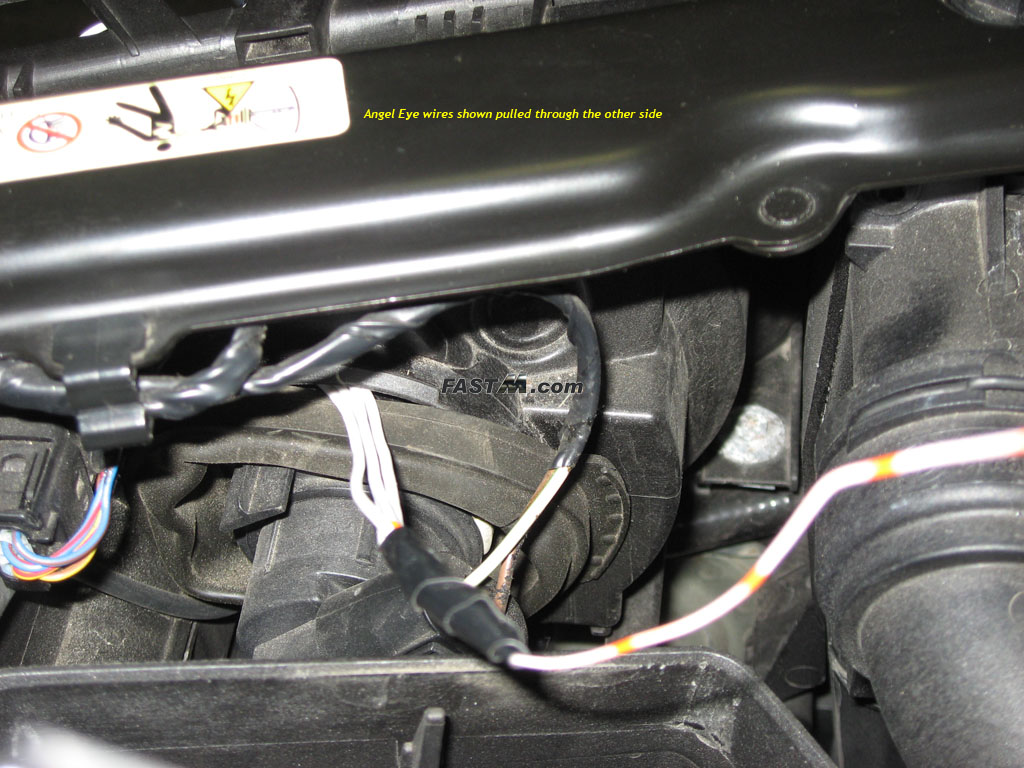
top to allow you to pass the Angel Eye wires through. 2e) Feed the Angel Eye wires from the front (above the reflector) to the back through the rubber boot. First tape each pair of wires together so that when
you pull them through you will know which pair is which. Second, to aid in the process, a sturdy wire will help you pull the wires through. Feed the sturdy wire through
from the front to the back and through the boot opening. Wrap the wire around the Angel Eye wires and tape it down with electrical tape. Now pull it through from the
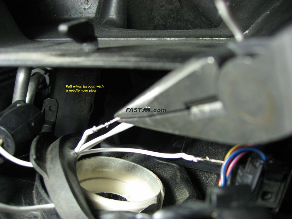
boot side. See pictures below. 2f) (Optional, not recommended, skip to step 2h) Make a small incision on the rubber boot with a small pocket knife. This will allow you to pass the wires through the boot and also allow you to reinstall the boot around the socket opening. Otherwise, you can always close the boot around the wires. 2g) (Optional, only if step 2f is performed) Feed the Angel Eye wires through the boot. Using needle nose pliers, grab
one of the Angel Eye wires by the terminal and stick it through the boot opening that you made in the previous step. Then on the other side of the boot, use your needle
nose pliers again to pull the wire through. Do this for the other 3 wires till all four wires are through. You can now reposition the boot and reinstall it. You can
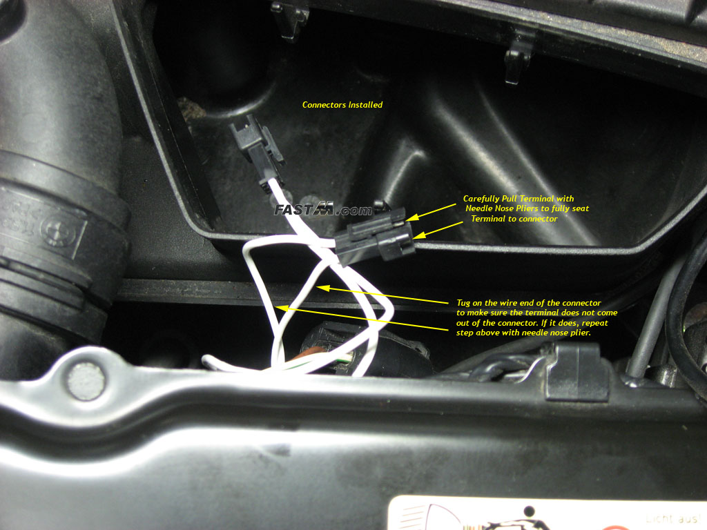
also reinstall the H7 bulb now. 2h) Install Angel Eye wire connectors. The polarity does not matter as long as you have the correct pair of wires. The wire terminal goes to the two outer
holes on the supplied connector. Do not install the terminal in the middle hole. Inserted the terminal through the connector and use needle nose pliers to tug on the
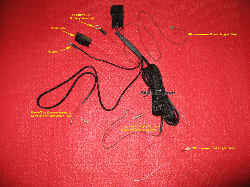
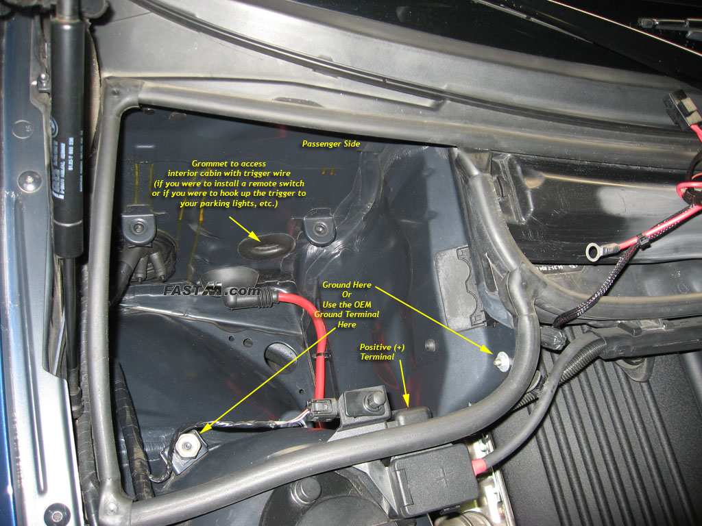
terminal end to insure it locks in place. Give the other end a light tug to make sure the wire does not come out of the connector. Step 3) Wire Harness Installation 3a) Lay the wire harness on top of the engine bay. The relay should be near the passenger side positive (+) battery terminal. See image below for the
correct positive terminal. The shorter end of the harness coming from the relay should follow the passenger fender to the passenger headlight. The longer end should
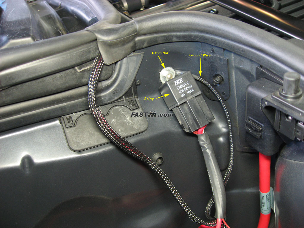
go across the engine to the driver's side fender towards the driver's side headlight. 3b) Ground the relay. Use a 10mm socket to remove the 10mm nut located in the passenger power terminal area. Mount your relay and ground here. The
ground wire is the short black wire coming out of the relay with a ring terminal at the end of it. See picture below. Optionally, you can utilize the factory 19mm ground
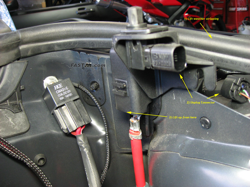
terminal as pictured in the previous step (step 3a). 3c) Route the short harness to the passenger side headlight. If you lift the weather stripping from the passenger side power terminal area, you can slide
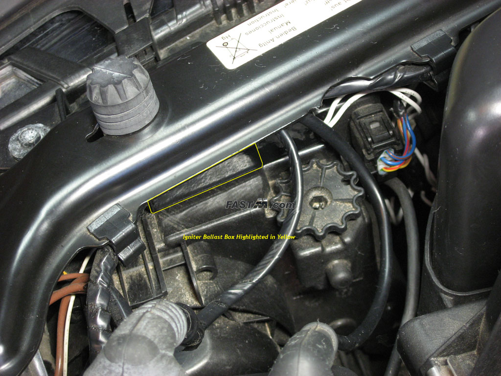
the harness under the factory harness bundle then route it down the passenger fender to the passenger headlight. 3d) Connect the black rectangular igniter ballast box to the harness (pictured below) and also to the passenger side Angel Eyes (not pictured). Do not mount
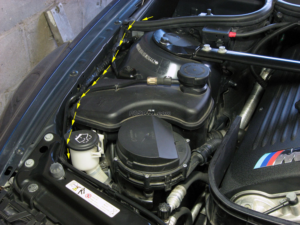
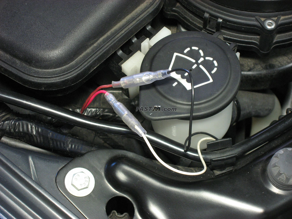
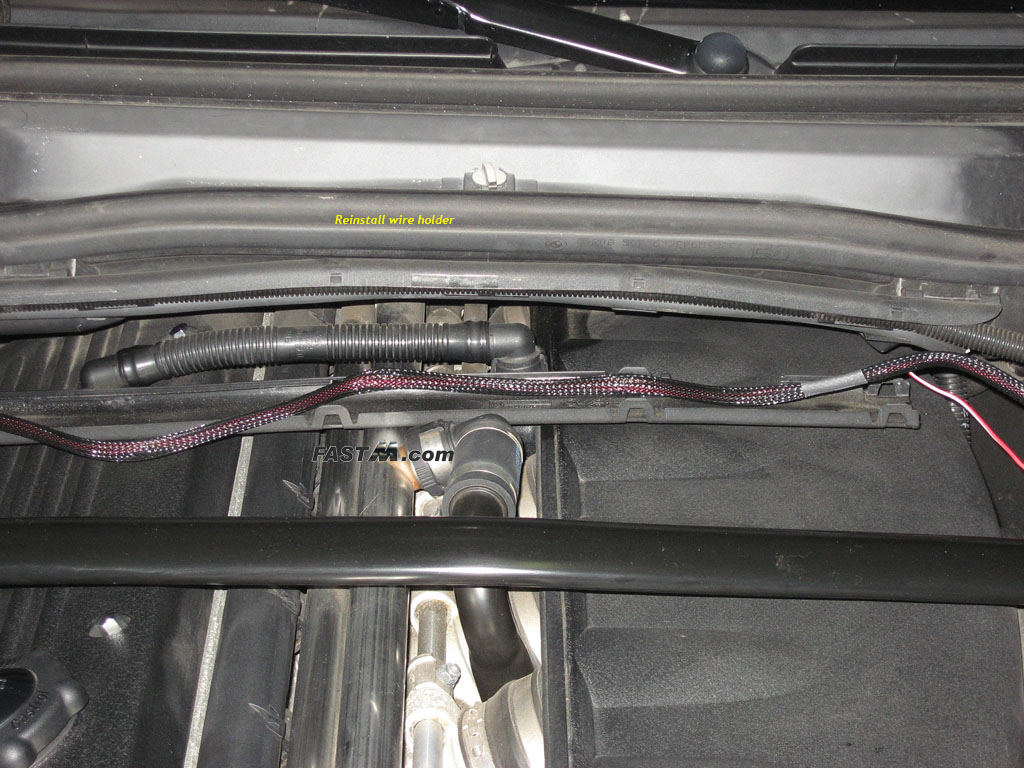
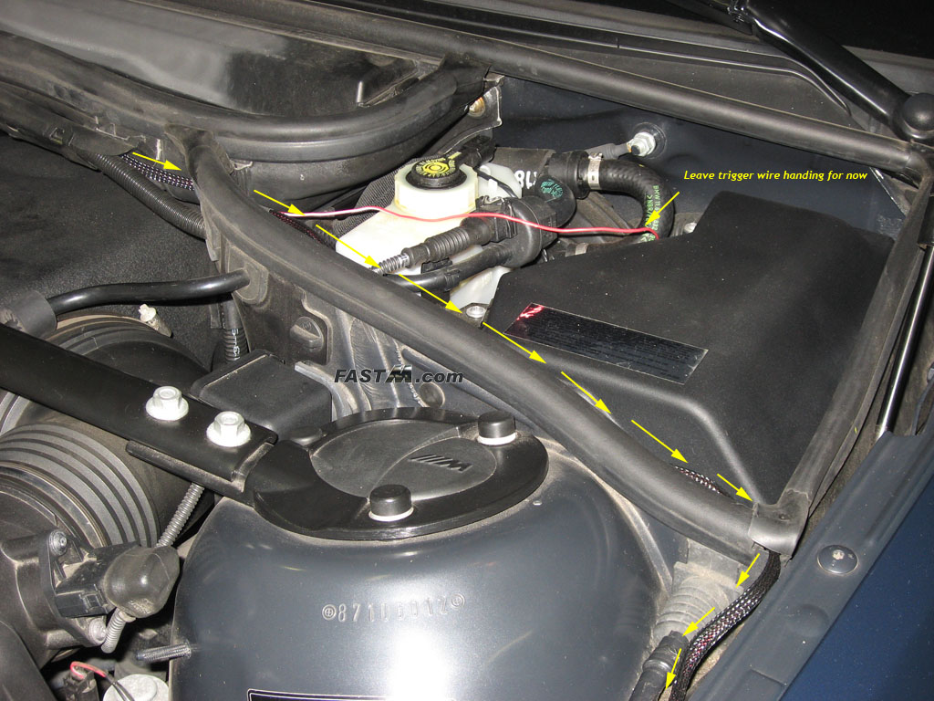
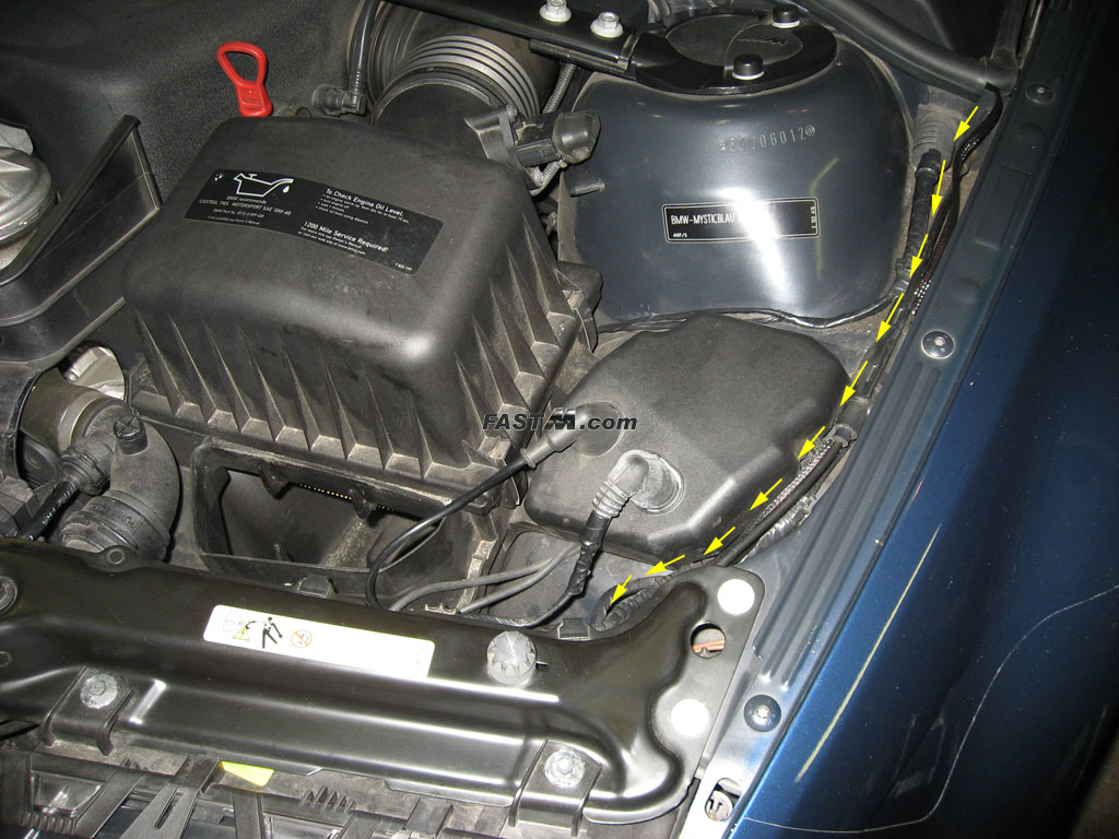
(tape) the igniter box just yet. 3e) Route the long harness across the top of the engine and secure it over the OEM wire holder. See pictures below. 3f) Route the long harness through to the brake fluid / ECU box area then down the drivers side fender. I chose to go through the OEM weather stripping as
pictured below. Leave the trigger wire in the ECU box area for now and run the harness down the drivers fender (being as neat as possible). 3g) Connect the black rectangular igniter box to the harness and drivers side Angel Eyes. Do not mount the igniter box just yet. 3h) Connect the red wire from the relay to the positive (+) terminal found in the power terminal area. 3i) You are now ready to test your Angel Eyes. Coming off the relay should be a second trigger wire that is brown. Have someone touch the brown wire to the positive terminal or use a clamp then examine if your Angel Eyes work. If all is good, remove the brown wire from the positive terminal. 3j) Assuming everything is in working order after testing it above, you can choose to mount the rectangular igniters now or wait till you are done with your install.
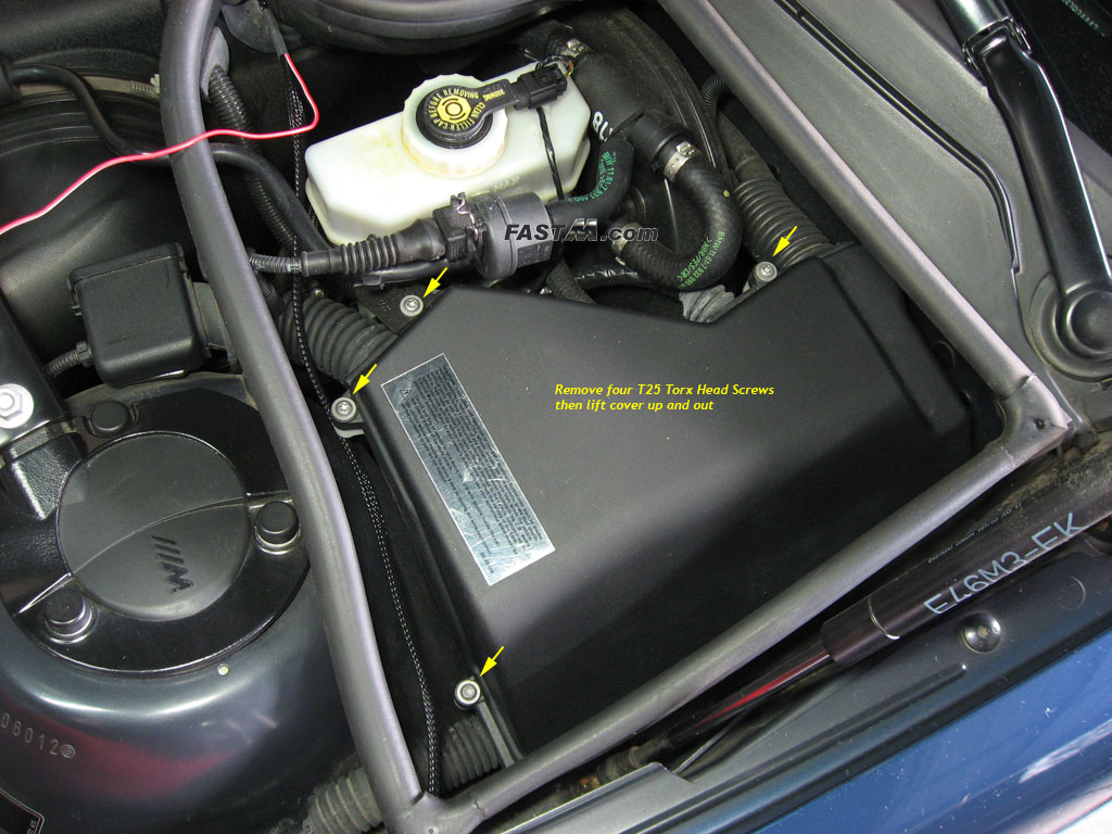
I secured mine directly on top of the headlight tucked under the radiator support where you can not see it. See image below. Step 4) Trigger Wire Installation Note: The Accessories wire method is one of many ways to wire the Angel Eyes. This method will allow you to have the Angel Eyes on all the time whenever the car is running. This is independent of whether your headlights/parking lights are on or off. When you turn off your car, the Angel Eyes will stay on for a few seconds since there is still power through the accessories wire. This will not cause any power drain issues as the Angel Eyes do not draw a lot of power. 4a) Open the cover to the ECU box using a Torx 25 bit to remove four Torx head screws. (Note: Some earlier cars might be HEX 27). Once the screws are
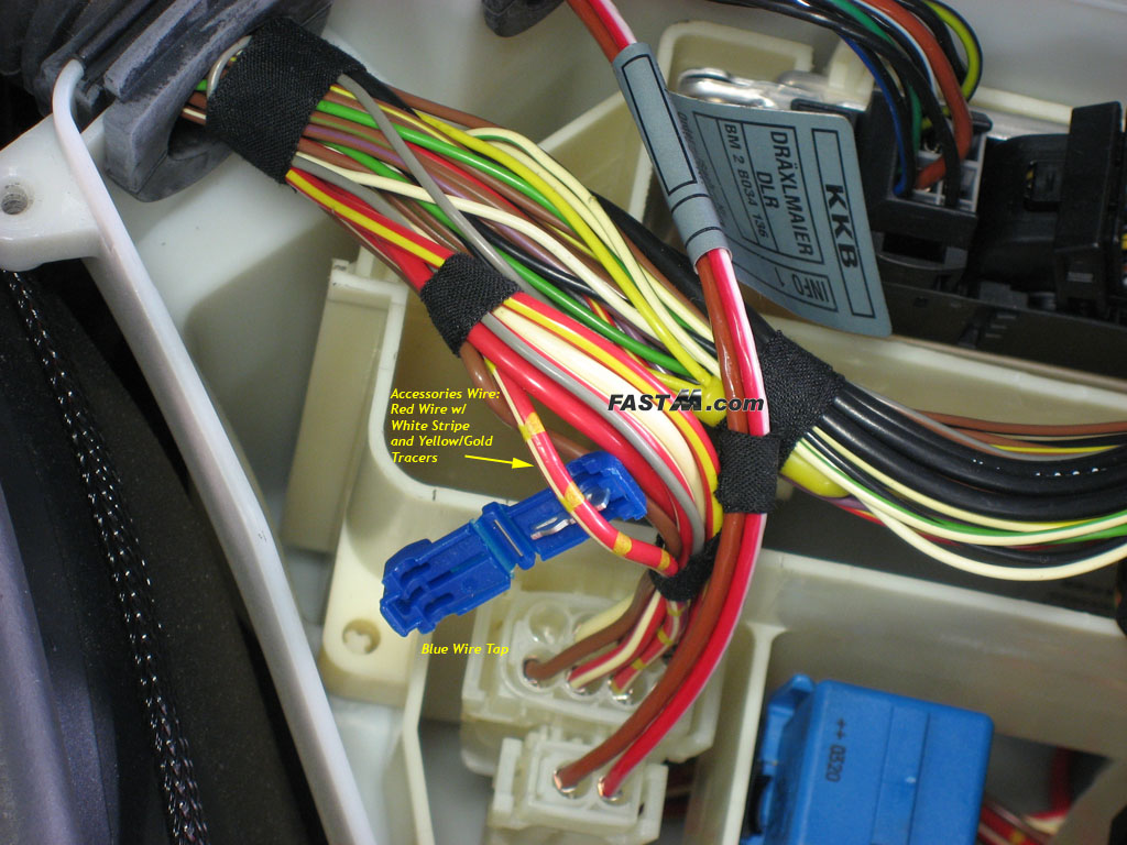
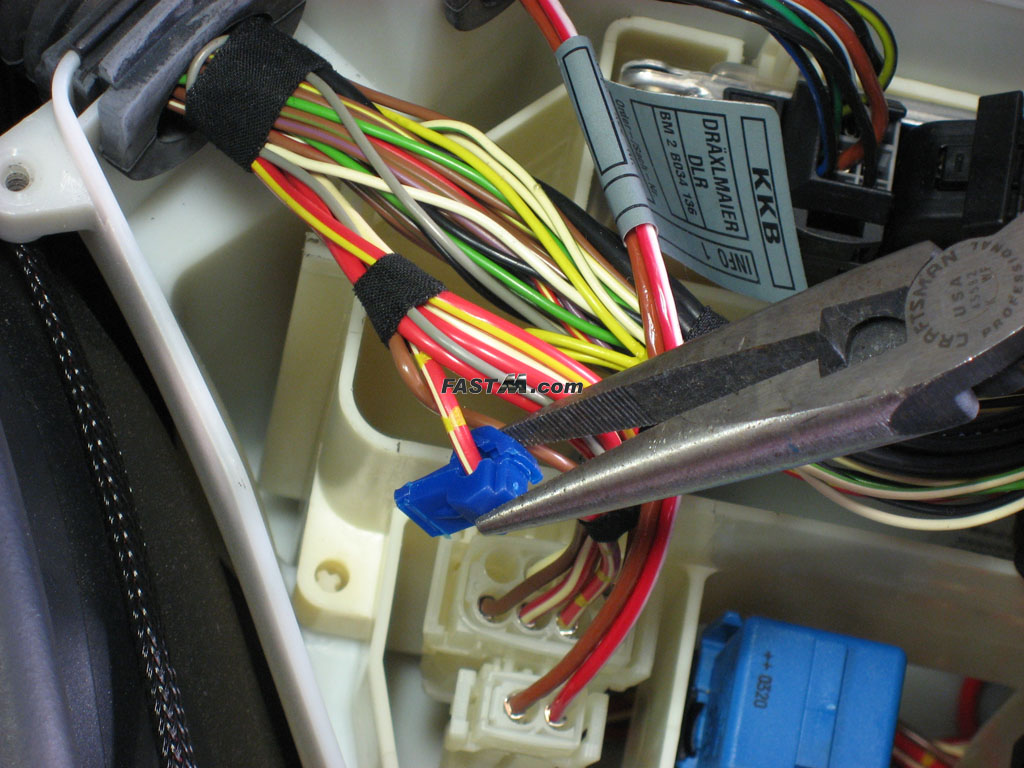
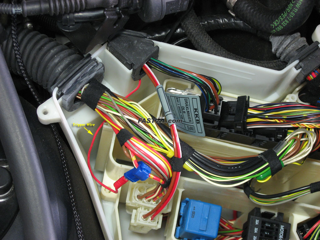
removed, tilt the cover up and pull out. 4b) Locate the red wire with white stripe and yellow/gold tracers. Install your blue wire tap using your pliers. DO NOT cut any wires or yank on any wires. 4c) Route the red trigger wire into the ECU box and connect the end to the blue wire tap. I chose to lift one of the rubber grommets and lay the red trigger
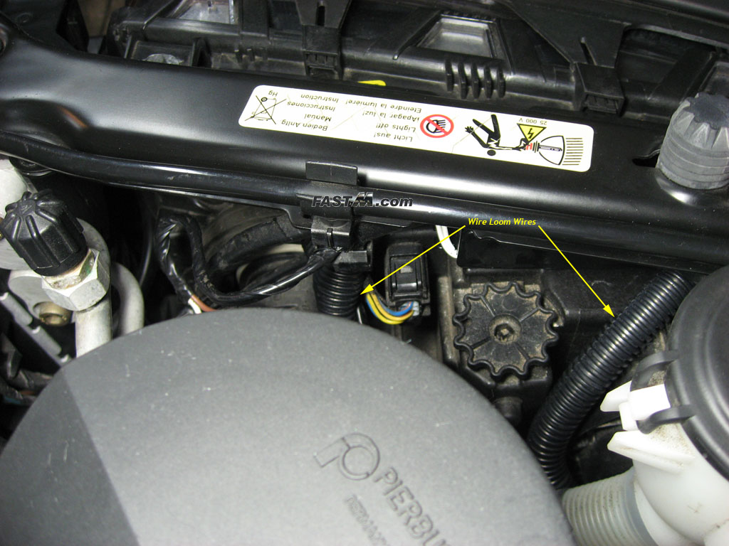
wire under. You can fish it through the grommet if you like for a more professional look. 4d) Test the Angel Eyes by turning your ignition to position 2. If your Angel Eyes light up then you are good to go and you can begin cleaning up the loose ends. 4e) Reinstall the ECU box cover at this point if your Angel Eyes are working ok. Step 5) Clean Up 5a) Tape the 2nd Trigger wire. If you are not using the second trigger wire (wire closest to relay), you should tape it using electrical tape and tuck it away. Make sure to tape up the connector end so that it doesn't accidentally get in contact with the frame of the car. 5b) Zip tie the harness. Using zip ties, secure the harness down along the fender, etc. Make sure no wires come in direct contact with the engine. 5c) (Optional, assuming you made a slit on the rubber boot from steps 2f/g) Use silicone or liquid electrical tape over the incision area on the rubber boot where the Angel Eye wires were installed. This should prevent any moisture from possibly getting into your headlights. 5d) With the lense still off the headlights, check the Angel Eyes to make sure they are still aligned and in the proper position. 5e) Reinstall your headlight inner bezel but DO NOT snap on the upper outer corner. If you snap it in place it will push the Angel Eye ring too close to your projector housing and possibly interfere with the self leveling adjustments. It will be fine to leave that one corner loose. 5f) Reinstall your headlight lense and trim following the reverse procedures you following for removal. 5g) Using some wire loom, dress up the wires coming from the back of the headlights, the wires from the igniter ballast to the harness, etc. 5h) If you did not mount the igniter boxes from step 3j, mount them now. You do not want those boxes bouncing around when you are driving. :-) I secured mine
directly on top of the headlight tucked under the radiator support where you can not see it. See image below. Step 6) Go out, drive your car, and enjoy your new Angel Eyes!!!
Disclaimer: This guide is for reference only to show you how I installed the Angel Eyes on my vehicle. I am not responsible for any injuries or vehicle problems you might have following this guide. Contact: If you have any issues with this product, please visit Umnitza's web site and contact them directly. I am not affiliated with Umnitza. |